ExplorerHAT & Scratch on Raspberry Pi
Introduction
If you want to do more with the Raspberry Pi GPIO pins beyond just blinking a few LEDs, the Pi Mironi ExplorerHAT is packed with a bunch of features. It has 4 analog inputs, 4 digital inputs, 4 digital outputs, two motor drivers, and 8 capacitive touch sensors. Interface to the GPIO pins on the Raspberry Pi through Scratch can be accomplished through either broadcast methods or setting the values of variables. Let's take a look at a few examples.
Scratch is an event-driven block-based programming language. It is assumed that you have a general working knowledge of using blocks, variables, and broadcast messages in Scratch. The blocks and features that are using are only in ScratchGPIO8plus and not yet supported in Scratch 2 or the pre-installed Scratch 1.4. If you haven't installed ScratchGPIO8plus, please do so before starting this activity.
Setup
|
This initializes the GPIO server application that listens to broadcasts and updates variables in Scratch. Broadcast message: gpioserveron |
 |
|
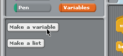
To set up the use of special ExplorerHAT options, create a variable called AddOn. Create a block to assign it to the value ExplorerHAT. Attach the broadcast gpioserveron block and the set AddOn to ExplorerHAT blocks to the when Flag is clicked event block. This makes sure that the script runs the initialization at the very beginning. The name ExplorerHAT is case-sensitive. In general, with programming and code, it is best practice to pay close attention to both the spelling and capitalizations. |
  |
Input & Output Control
Basic input / output control using Scratch is accomplished using the broadcast message block. The easiest way is to create a new broadcast message for each command.
|
LED control There are four colored LEDs under the touch pads. These can be controlled with a simple broadcast message. Broadcast message: led#[on/off] |
 |
|
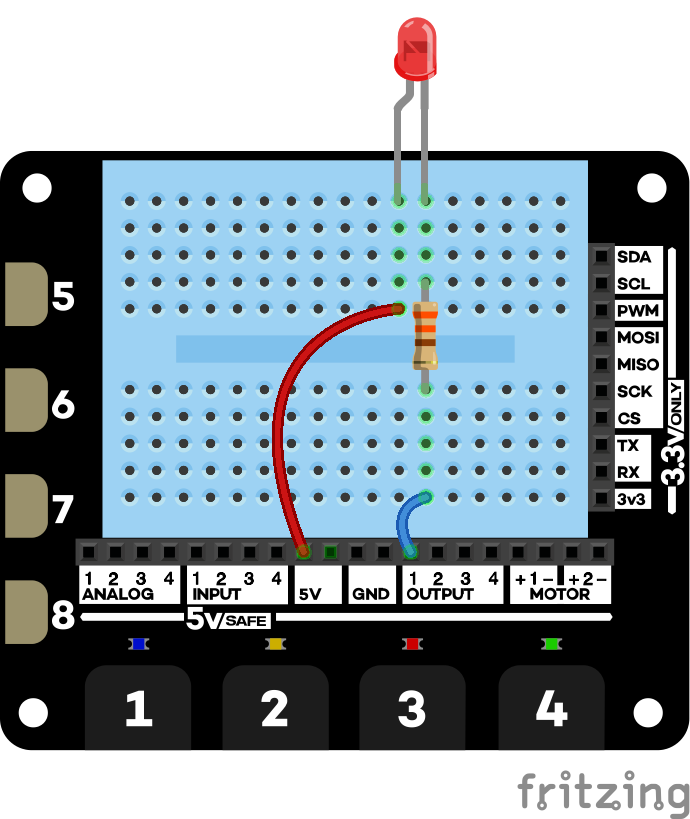
OUTPUT control - (OUTPUT1 - OUTPUT4) Four controllable outputs on the ExplorerHAT. These are active LOW OUTPUTs (Sinks to GND). Note: This is inverted compared to the normal GPIO control of pins as HIGH / LOW. To turn on an LED, wire LED to 5V and connect negative leg to output pin (through current limiting resistor) Broadcast message: output#[on/off] |
Wiring Example
Cold Block Examples
|
Motor control - Motor1 and Motor2 The speed of the motors can be controlled to spin CW and CCW by sending it a value between -100 and +100. Connect the two wires (red/black) from each motor to the + and - pins. The structure of the command is: Broadcast message: motor#speed[value] |
 |
Using variables to simplify the broadcast messages
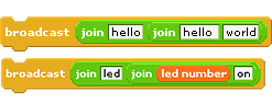
You can also uses variables and the join block to create your own broadcast messages in the code. Here's an example that blinks a random LED on and off.
|
Here are all of the blocks that you're going to need for this. Create a variable called led number. You're going to use the pick random block to randomly pick which LED to turn on. You need the led number variable block, the broadcast block, and two join blocks. |
 |
|
You're going to use the two join blocks to join three elements together into a compound broadcast message. Drag one join into the second space (world) of the first join. Now, change the text so that it joins the text led with the variable led number and the text on. |
 |
Putting it all together. Here's the complete script that picks a random number from 1 to 4, and blinks that LED - turning it on for one second and then off for one second. You can use the join block and variables to control any number of other features in scratch.
|
 |
Touch Input
There are four points that use capacitive touch to detect a touch input. These are labelled 1, 2, 3, & 4. There are four additional clip points that can be used with alligator clips to connect to a variety of conductive objects to use as digital sensors.
|
A 'touch[#]' broadcast message is received when one of the tabs is touched. You can use the "When I receive [ ]" event block to define what happens when a touch is received. You must clear the touch event by broadcasting a message: "touchreset" If you don't it won't be able to detect another touch event. |
Example:
|
Connecting Other Inputs
There are four points that use capacitive touch to detect a touch input. These are labelled 1, 2, 3, & 4. There are four additional clip points that can be used with alligator clips to connect to a variety of conductive objects to use as digital sensors.
|
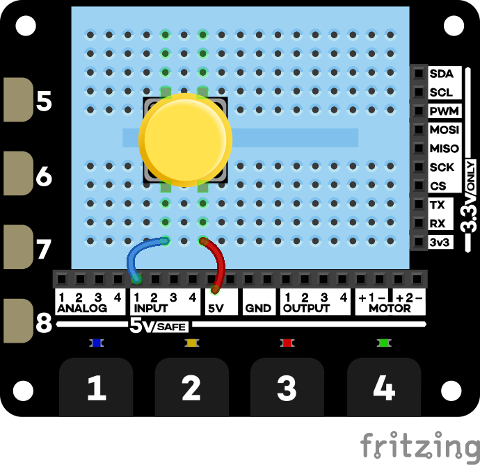
Digital Inputs A digital input is something like a switch. It is either on (1) or off (0). The on state indicates that it's connected to 5V. Here is a simple example using a button switch. Connect up the circuit shown. When you push the button, you connect the input pin to 5V. In Scratch, the value of the inputs is stored in a variable that is called input#. If the variable does not exist already, create a variable for the input that you want. In this case, it's called input1 We've included a quick example showing how to use the button press to turn on the LED. |
Wiring Example:
Code Example
|
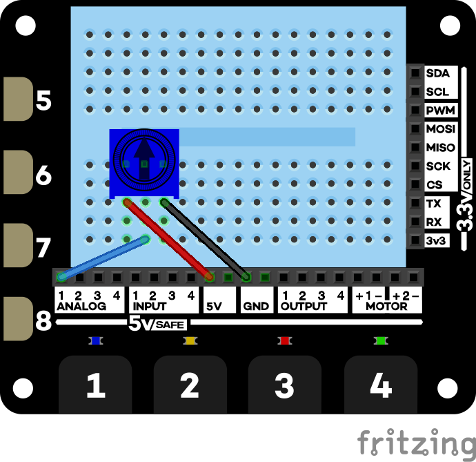
Analog inputs An analog input can measure not only on and off, but variations in between. It converts a voltage into a value that you can use in the code. Here, we are using a potentiometer - or a variable resistor - as a sensor. When connected like this, the variable resistor works as a variable voltage divider. As you twist the knob, the voltage out of the middle pin changes. The electrical symbol for a potentiometer looks like this. It has three legs. Connect the opposite legs to 5V and GND, and the middle let to analog1. Under the sensor block, you'll find an option for analog1 and adc1. How do the values compare? |
Code Example One quick way to view the values of the sensor is to use the "say" block. Twist the knob all the way in each direction. What range of values do you see?
|
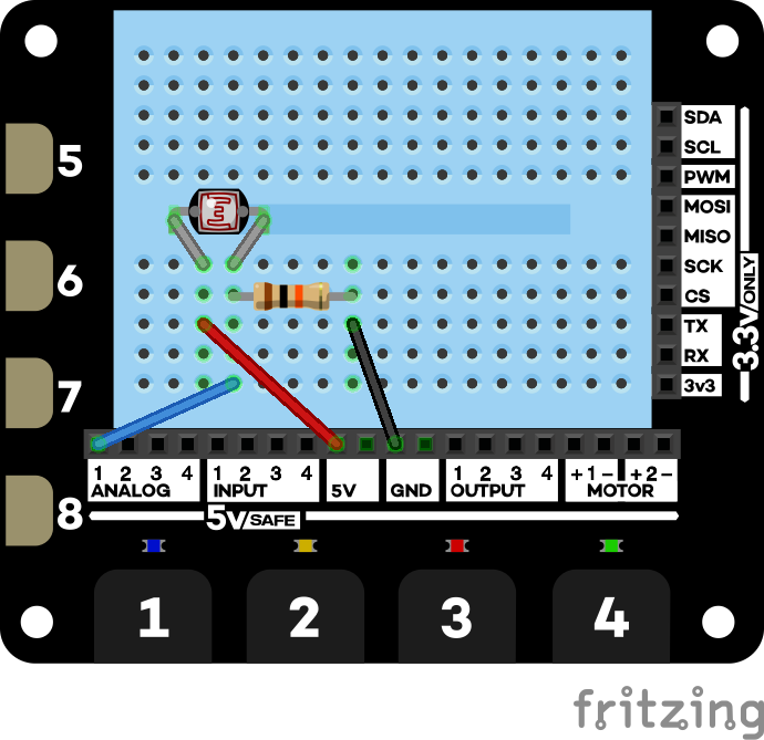
Light Sensor Example Here is a wiring example of connecting up a photocell (light detector). The circuit diagram for this looks like this. Vout of the sensor is connected to the analog1 input pin. What range of values do you see with this? |
 |

Design Challenges
-
Marquee - Light up the LEDs one on after another
-
Zippy - Light up the LEDs one on after another where it progressively gets faster and faster
-
Sparkles - Light up the four LEDs in a random pattern for a brief (100 ms) time - repeat 10 times.
-
Touch Response - Use these blocks to see if you can write a program that will light up the led that you touch.
-
Light Sculpture Challenge - Use the OUTPUTs and external LEDs. Extend these using Male-Female jumper wires to move the LEDs off the breadboard to create your own light sculpture.
-
Button Sequencer - Use a button press or a touch response to sequence each light to turn on one at a time.
-
What do you want to do?
Want to do more? Check out the ExplorerHAT Python library